
Thursday, September 27, 2012
Wednesday, September 19, 2012
Test 3 - Filling Truth Tables
Two logic gates are the AND gate and the OR gate. Complete the truth tables for these two gates:


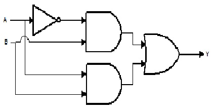
Test 2- Design a Logic Circuit for a Burglar Alarm System
Design a Logic Circuit for a Burglar Alarm System for a house which has 2 windows and 2 doors.
Friday, September 7, 2012
NAND & NOR GATES
The NAND gate
This is a NOT-AND gate, that is an AND gate followed by a NOT gate. It acts in the manner of the logical operation "and" followed by negation. The outputs of all NAND gates are high if any of the inputs are low. The symbol is an AND gate with a small circle on the output. The small circle represents inversion.

A NAND GATE with 3 input

The NOR gate
The NOR gate is a combination OR gate followed by an inverter. That is a NOT-OR gate is equal to an OR gate followed by a NOT gate. The symbol is an OR gate with a small circle on the output. The small circle represents inversion. Its output is "true" if all inputs are "false." Otherwise, the output is "false."

Thursday, August 23, 2012


Monday, April 25, 2011
Logic Gates
Hello dear Students,
Below are some notes on Logic Gates. We have covered this part in today's class. So please understand the notes and share your understanding with your peers.
Logic gates
Digital systems are said to be constructed by using logic gates which are the elementary building block of a digital circuit.
Logic gates process signals which represent true or false. Normally the positive supply voltage +5Vs represents true (1) i.e. the high state and 0V represents false (0) i.e. the low state.
The logic state of a terminal can, and generally does, change often, as the circuit processes data.
Most logic gates have at least two inputs and one output. At any given moment, every terminal is in one of the two binary conditions low (0) or high (1), represented by different voltage levels.
Truth tables
A truth table is a good way to show the function of a logic gate. It shows the output states for every possible combination of input states. The symbols 0 (false) and 1 (true) are usually used in truth tables.
The AND gate
The AND gate is an electronic circuit that gives a high output (1) only if all its inputs are high. The AND gate is so named because, if 0 is called "false" and 1 is called "true," the gate acts in the same way as the logical "and" operator.
A dot (.) is used to show the AND operation i.e. A.B (Bear in mind that this dot is sometimes omitted i.e. AB)
The OR gate
The OR gate is an electronic circuit that gives a high output (1) if one or more of its inputs are high (true). If all the inputs are low (false) then the output is low (false). A plus (+) is used to show the OR operation. The OR gate gets its name from the fact that it behaves after the fashion of the logical inclusive "or".
The NOT gate
The NOT gate is an electronic circuit that produces an inverted version of the input at its output. It is different from other electronic gates; it has only one input and one output. It is also known as an inverter. It reverses the logic state.
If the input variable is A, the inverted output is known as NOT A. This is also shown as A', or A with a bar over the top, as shown at the outputs.
Friday, March 4, 2011

Subscribe to:
Posts (Atom)